
Translation: G- and M-codes for CNC machines - simple about complex
Machine complexes with CNC use a variety of software for their work. However, you can control the equipment using the same control code. It is the ISO 7-bit alphanumeric digital language based on international standards ISO and EIA.
- What are G and M functions for CNC?
- G and M codes for programming CNC machines – what is it?
- G-functions for CNC machines
What are G and M functions for CNC?
Most manufacturers of CNC systems describe the basic parameters using ISO standards, but often deviate from the rules in their equipment to expand the capabilities of the systems.
Japanese companies in their FANUC CNC systems widely reveal the potential of using G and M codes. Their equipment was one of the first to work on the ISO 7-bit language. Now these are the most common control panels in the world.
G-codes set the CNC for a specific action. M-codes, on the other hand, are auxiliary, controlling the modes of operation of the equipment. For example, the command G01 is used to move the tool along a straight trajectory, while the code M06 is used to replace the tool.
G and M codes for programming CNC machines – what is it?
Settings for CNC equipment are written in various languages, but a basic set of G and M commands is sufficient to create a control program.
G-code (NC-code)
The G-function is a programming language that performs preparatory functions for the machine tool controlled by axis movement.
The "7-bit ISO" was created by EIA in the 60s of the last century and revised 20 years later. The G-code is approved as ISO 6983-1:2009 standard, and in the USSR as GOST 20999-83. The code records information on an eight-track punched tape and encodes 128 characters.
Note: many manufacturers customize the code according to their own, and differences from the base can be found in the instructions for the specific control system.
In a program written in the ISO 7-bit language, all commands form frames – collections of one or more commands. The first frame consists of a single sign – "%". Sometimes such a symbol is also present in the last frame. This is how the program separates the frames from each other. The remaining frames are numbered, and they end with the CR/LF – line feed. To end the program, the command M02 or M30 is input.
Comments are written in parentheses and contain specific information:
- time and date of program creation;
- part number;
- blank material;
- tool dimensions;
- work area data;
- operation name.
Note: The CNC does not read text in parentheses.
More often than not, the list of codes in the frame begins with preparatory ones. Then, movement commands are input, followed by operational mode selection and technological codes.
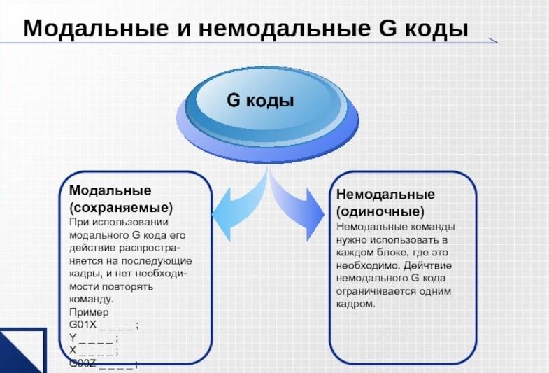
Modal and non-modal G-codes.
Independent parts of the main program are described between the designations M02–M30. The number goes first, and M17 is written at the end.
M-code
M-functions are additional codes and may differ slightly on different CNC machines. These commands control the working tools and equipment modes with CNC.
Auxiliary commands are used alone or in conjunction with other codes. When a frame sets a working tool in the spindle, it looks like this:
N10 T2 M6, where:
- T2 – tool number 2;
- M6 – tool changeover.
Here, the M6 command on the control panel implies a set of actions to replace the working tool:
- tool preparation for replacement;
- spindle rotation shut off;
- placing the new tool in the magazine;
- replacement.
If the M-code includes any device, then its counterpart, which turns it off, must exist:
M8 – M9 – turn on/off the cooling system;
M3 – M5 – turn on/off the spindle speed.
More M-codes are used in the control of machines with an impressive set of interchangeable devices.
Note: M-code can be input independently or within a frame with G-codes.
Auxiliary commands are divided into:
- standard – control devices equipped with almost all machines (cooling systems, spindles, working tools);
- special – interact with the working modes on one or several machines of the same model: tighten/loosen the rotating axes, turn on/off the measuring head.
Important: the same commands on different machines can be configured to control other devices.
Table of G-codes with decryption
The table presents a partial list of commands for controlling the machine, only the important ones:
- tool slide movement with a specified speed in a circle or straight line;
- performing sequential actions – drilling, threading, grinding;
- control of settings in the Cartesian coordinate system and working area.
| Codes | Code description |
|---|---|
| G00-G03 | Tool movement to specified positions |
| G17-G19 | Switching working planes (XY, ZX, YZ) |
| G20-G21 | Not specialized |
| G40-G44 | Tool length and diameter compensation |
| G53-G59 | Coordinate system switching |
| G80-G85 | Drilling, reaming, thread cutting phases |
| G90-G91 | Coordinate system switching (absolute, relative) |
Table of M-codes with decryption
Auxiliary commands of the program code are marked with the letter M and execute the following actions:
- tool replacement;
- control of cooling on/off;
- spindle start and stop;
- start and end of a subroutine.
| Code | Code purpose |
|---|---|
| M00 | Temporary stop of the machine tool until the "Start" button is pressed again |
| M01 | Interruption of equipment operation until the "Start" button is pressed, if the stop confirmation mode is activated |
| M02 | End of the program without reverting modal settings |
| M03 | Spindle start, rotate clockwise |
| M04 | Spindle start, rotate counterclockwise |
| M05 | Stop the spindle revolutions |
| M06 | Tool change |
| M07 | Start additional cooling |
| M08 | Main cooling start |
| M09 | Equipment cooling systems stop |
| M13 | Simultaneous start of coolant and spindle rotation clockwise |
| M14 | Simultaneous start of coolant and spindle counterclockwise rotation |
| M17 | Subprogram end |
| M25 | Manual tool change |
| M97 | Activation of an independent part of the program within the main one |
| M98 | Start of a subprogram separate from the main one |
| M99 | Subprogram shutdown |
| M30 | End of the program and reset of all settings |
1 code per frame.
G-functions for CNC machines
| Code | Code description |
|---|---|
| Movement along the axis | |
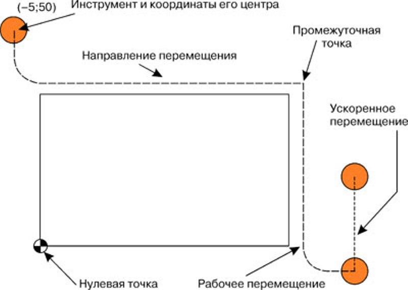
| G00 | Rapid or idle movement – very fast movement to a specified point. Not used for processing. |
| G01 | Linear interpolation – movement along a straight trajectory at a specified feed rate. Working movement |
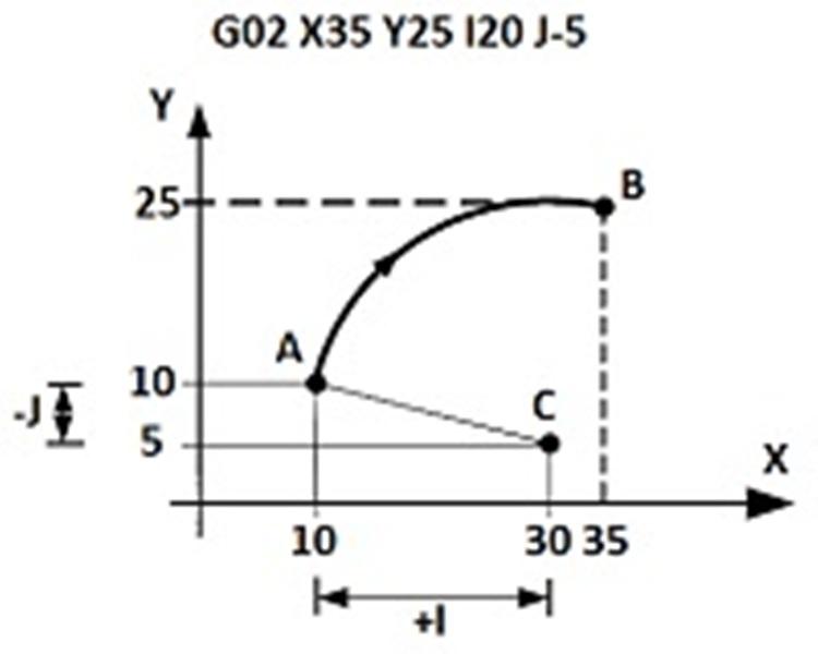
| G02 | Circular interpolation – movement along a curve to the right at the programmed feed rate |
| G03 | Circular interpolation – movement along a curve to the left at the specified feed rate |
| Set-up | |
| G20 | Input of inch values |
| G21 | Input of metric information |
| G90 | Absolute positioning – all coordinates measured from a fixed zero point |
| G91 | Relative positioning – all coordinates calculated from the previous position |
| Work with holes | |
| G81 | Drilling phase |
| G82 | Drilling cycle with dwell at the bottom of the hole |
| G83 | Interrupted drilling cycle |
| G85 | Reaming mode |
Up to 4 codes per frame.
G-code for circle with center coordinates.
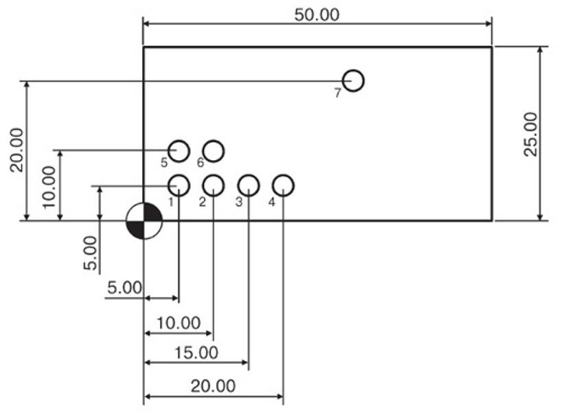
G-code for drilling holes.
Additional designations for programming CNC machines
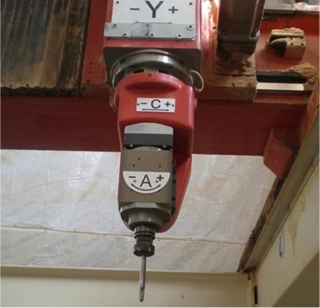
Movement coordinates of the tool in Cartesian planes – X, Y, Z.
Rotation around the X, Y, Z axes – A, B, C.
Circular interpolation parallel to the X, Y, Z axes – I, J, K.
R – radius, in repeating periods – tool positioning from the discharge plane, in rotation command – angle of coordinate system rotation.
D – tool radius compensation parameter.
H – tool length compensation value.
F – feed rate setting.
S – main movement parameter.
T – tool number value, to be changed by tool changer rotation.
N – frame number of the control program.
/ – skip the frame that does not need to be executed, placed before the frame.
(…) – comments in the control program.
The 7-bit ISO code is the main one for modern domestic CNC lathes. The encoding rules for a machine with a specific CNC device are determined by the common code used, the equipment operation manual, and the CNC system programming guide.
