
Programming CNC machines from scratch to professional level
Programming CNC is an important part of the design and production process. The cleanliness of the code affects the time it takes to test, debug, and launch the part into production. Numerically controlled machines differ in their purpose and methods of programming.
- Types of CNC machines
- CNC machine programming
- Programming methods for CNC machines
- How to create programs for CNC machines?
- Types of software
- Programming CNC machines
- How to write a CNC machine program from scratch?
- Tutorials for beginners on the basics of programming CNC machines
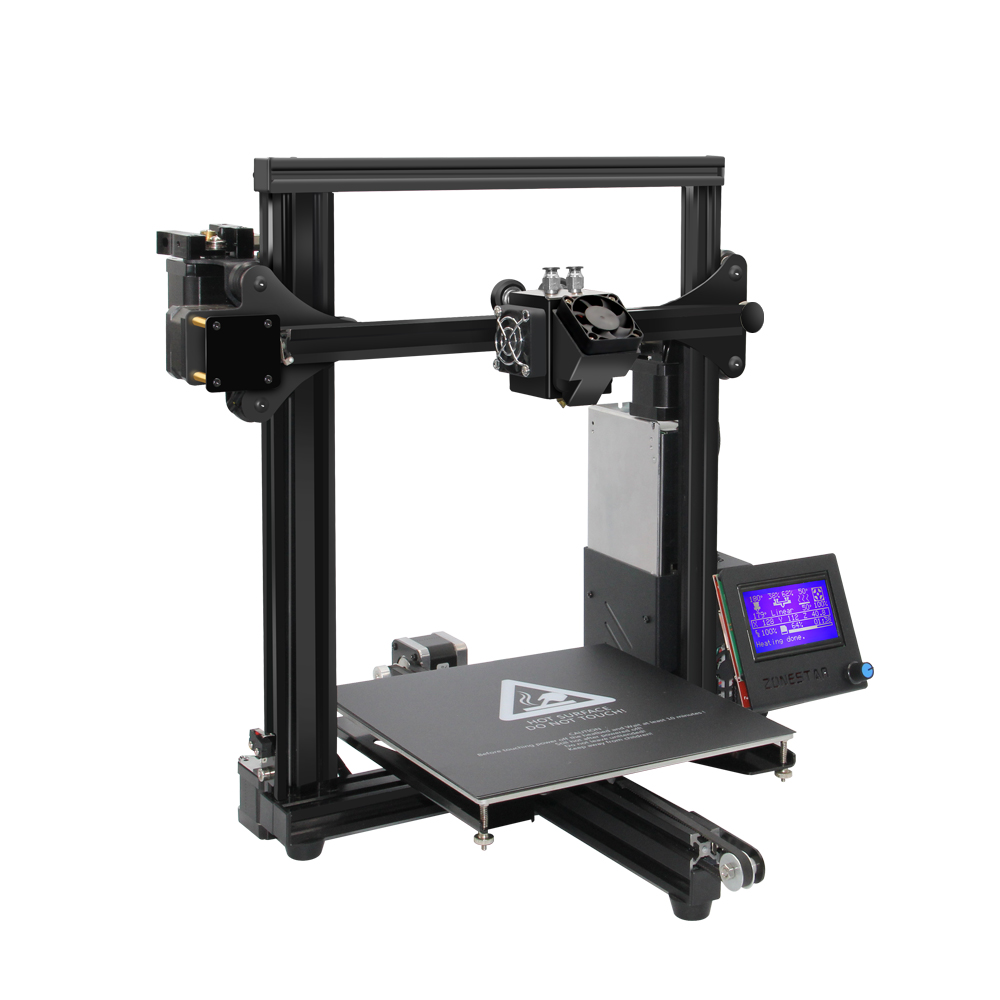
Types of CNC Machines
The same part can be processed on different machines. Depending on the geometry of the model, the presence or absence of holes, the part may undergo several sequential technological operations on different CNC machines:
- lathe - for shaping, cutting, grooving, undercutting;
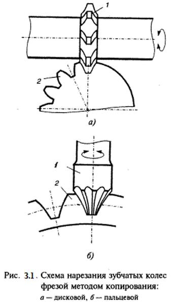
- milling - for cutting planes, creating ledges, grooves;
- drilling - for creating technological holes and countersinking;
- grinding - for final or rough processing of parts, removing welded seams;
- universal, which performs all the operations of the previous machines.
Usually, there are different types of CNC machines in an enterprise, which allow all the necessary technological operations to be performed for the creation of both simple serial parts and complex models in terms of stereometry.
CNC Machine Programming
In order for the equipment to perform operations, it is necessary to define a set of commands, the so-called G-code. It is transformed from a program written by the developer in a postprocessor. From here, the machine control system receives information about the task and its execution stages, then forms the profile, and the machine carries out technological operations.
In order to implement engineering designs or developments, it is necessary to write a program to create a specific part. This is done by a programmer using CAD software.
Important! Depending on the generation of the machines, the type of equipment, different programming platforms are used.
Programming Methods for CNC Machines
There are several ways to write programs for CNC equipment:
- manual - the developer or designer creates code on a remote PC, then transfers the finished program to the machine using a CD, flash drive, floppy disk, or via an interface cable;
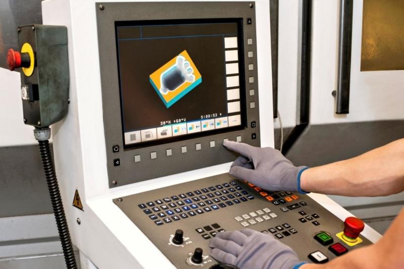
- from the CNC panel - the operator enters a set of preinstalled commands from the keyboard, which the machine then carries out;
- automated by using integrated CAD/CAE/CAM systems.
Important! Automated methods are only applicable to the latest generation machines, included in a unified computer system of the production process.
Manual programming is most commonly used for monotonous and simple turning work, for milling machines to process in two coordinates, and for drilling groups of holes.
Programming from the control panel allows to launch the same operations as with the manual method, plus transitions during 2.5-3-axis movements. This method is convenient for running monotonous operations or adjusting current ones.
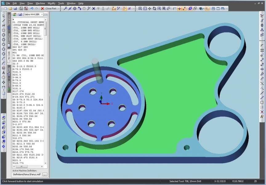
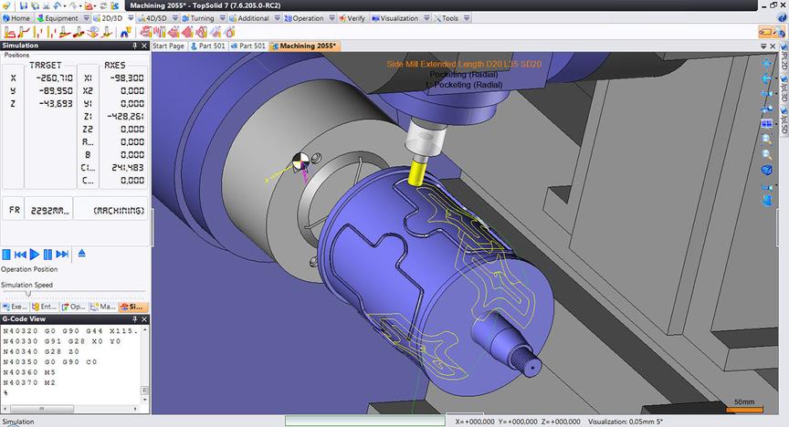
The most complex and flexible system is programming in CAM environments. Here, you need to first obtain a sketch and model from CAD, choose the machine in the dialog box, define fixtures, movement limits, tools, modes, processing methods, and corrections. The postprocessor, upon receiving the data, converts it to generate the control system. At the same time, the operator can see the virtual model in remote mode and make real-time adjustments to the equipment's operation.
Manual Programming
The vast majority of enterprises use machines programmed manually. This is due to the fact that the primary operations performed are simple and monotonous. Therefore, there is no need to acquire modern machines integrated into a unified electronic system.
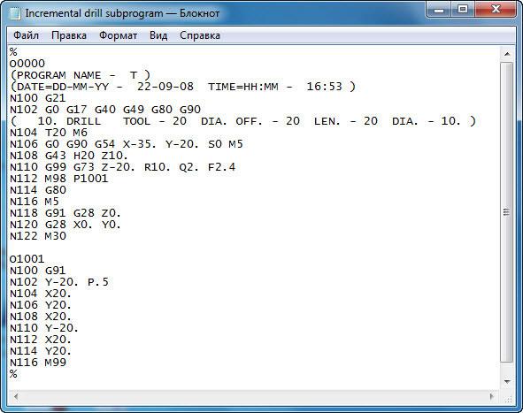
Manual programming requires meticulous accuracy and consistency of parameters. The operator must be proficient in G-code and know all its commands. The production process technologist creates the program on his computer in a text editor. The file extension is .txt. The program includes coordinates, according to which the tool moves, processing the part, and a set of codes. After writing the program, it is transferred to the machine's control system.
Important! For small enterprises or small-batch production, CNC machines with manual programming are an optimal solution. They cope with work effectively, and the technologist or operator only needs to write the necessary programs once, or write them infrequently - as needed.
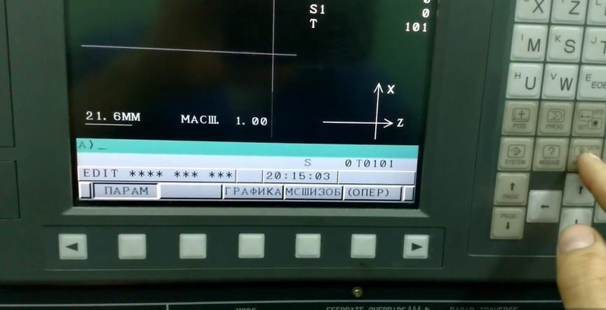
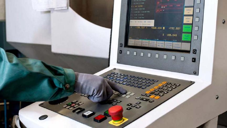
From the Control Panel
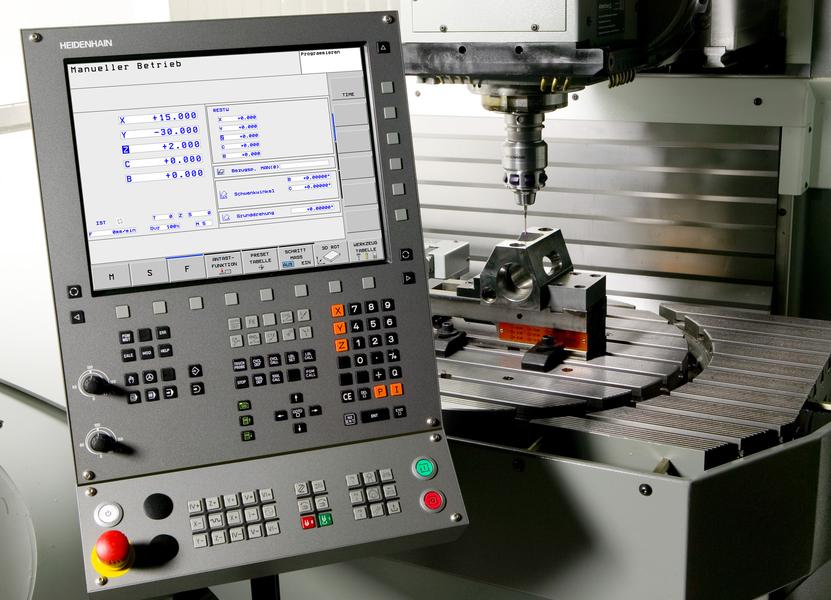
Many CNC machines are equipped with a display and keyboard. Therefore, the task can be set from the control panel directly. Manufacturers have provided two options for setting the task to the machine:
- inputting G and M codes from the keyboard;
- using a dialog box.
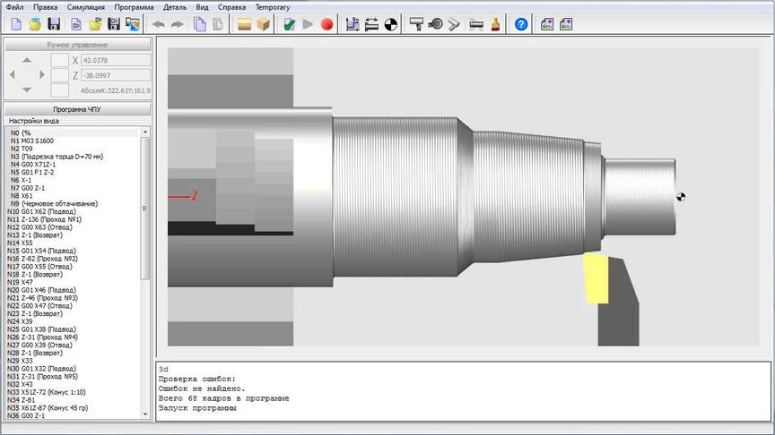
Important! CNC machines equipped with a display allow for simulation of part processing with visualization on the screen. This option allows for debugging the program before launching the machine.
Automated
For enterprises producing high-precision and complex configuration parts, a CAM system is considered optimal. It significantly increases productivity, as it automatically computes the tool path for processing the workpiece.
Enterprises where CNC machines perform a wide variety of technological operations also prefer fully automated equipment. This is because the time spent on manual programming will be incomparable to the machine's working time. You either have to substantially increase the number of technologists and operators or switch to an automated system.
Advantages of automated systems:
- ease technologist or designer from cumbersome and lengthy mathematical calculations,
- generate G-code (CNC machines) on the same base language for all types of machines,
- have a set of ready-made functions that shorten the time of programming,
- load the finished code into the machine's memory directly from the technologist's PC.
Important! CAM systems can be either language-based or graphical. The former require knowledge of a specific programming language, the latter converse with the developer in interactive mode and are much easier to learn.
How to Create Programs for CNC Machines?
To write a program for CNC equipment, specific rules must be followed:
- consider the part as a geometric body;
- the interaction of the tool and the workpiece should take into account their simultaneous movement relative to each other;
- the trajectory of the tool is defined by its center;
- the tool moves from one area to another, and these areas can be arcs, curves, or straight lines;
- intersections (reference, or nodal points) are included as coordinates in the control program;
- G-code is created frame by frame, with each frame corresponding to a description.
The more complex the part, the more frames the control program will contain.
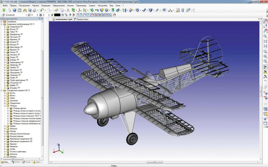
CAD Models
Since the appearance of PCs, automatic design systems have been called CAD systems. However, the abbreviation "CAD" is still firmly established, and technologists, developers, programmers, and designers of any design software still refer to it as CAD.
Main CAD models:
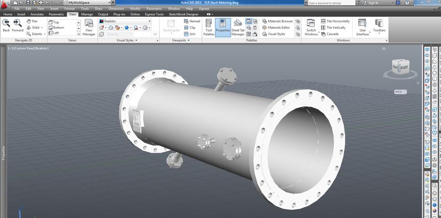
- AutoCAD - a leader among all systems, a program that allows programming in 2D and 3D environments. In AutoCAD, you can construct drawings, three-dimensional models, and more. In addition, this is platform software, meaning it is not narrowly specialized, but intended for any type of design - mechanical, automotive, road, etc.
- Bricscad - an alternative to the previous software. Includes parametric modeling tools and directly supports DWG format and BIM technologies.
- Autodesk Inventor - a professional 3D design system for industrial production. This software supports the import of models and files from other CAD systems, integrates with other software in the line - 3ds Max, AutoCAD, Revit, and others. It is adapted for Russian standards in design, calculations, modeling, and documentation creation. It includes a large set of standardized models, functions, parameters, and tools.
- KOMPAS-3D - domestic software for parametric modeling. Designed for engineering, construction, and instrumentation. Fully supports ESKD and GOST.
- PTC Creo - "heavy" CAD system for parametric design of large assemblies (for example, for aviation or shipbuilding).
- NX - designed for modeling and designing complex products, including complex assemblies. Works on almost any OS, supports cross-functional multi-user team, advanced capabilities for industrial design. This software even allows modeling the behavior of mechatronic systems.
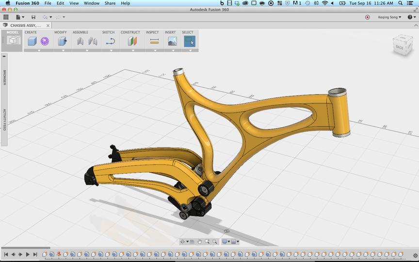
- Fusion 360 - a cloud-based CAD system that works in a virtual environment. It preserves most of the functions of desktop software, while allowing remote user interaction.
Important! When choosing software, it is important to consider the tasks faced by the technologist or designer, the volume of work, the software's capabilities, and its integration into the general electronic production system.
File Conversion
Enterprises using outdated software often face the problem of opening files created in newer versions of software or programs, the file extensions of which are not supported or understood by the old program.
Replacing software with new one is not always possible: licensed software is expensive. In addition, modern programs simply will not work on outdated PCs with Windows XP or 7. Replacing the computer park altogether is not affordable for many enterprises.
Therefore, designers have three ways - to install free software that supports the required file format, to use cloud-based software, or to use special converters.
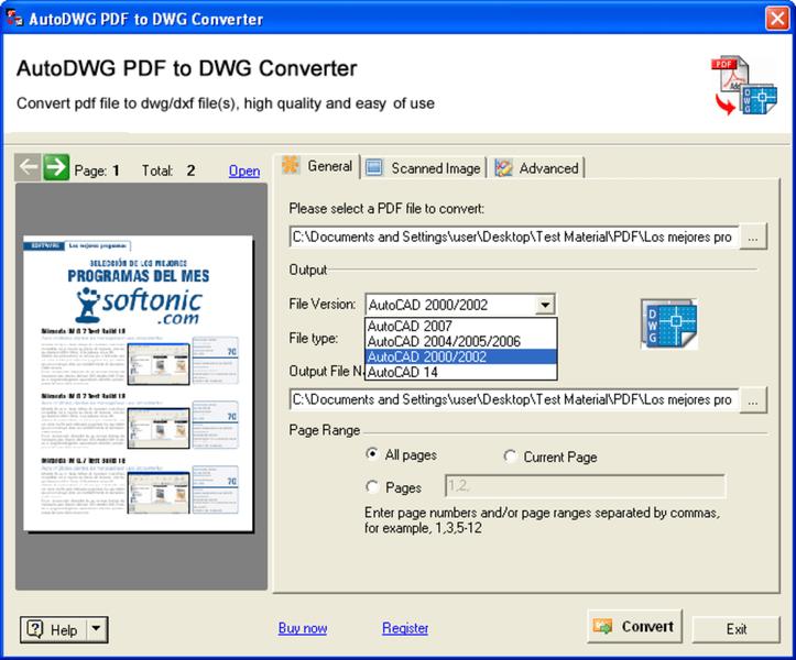
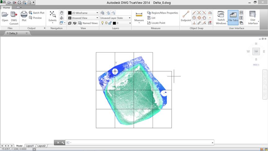
Autodesk has released DWG TrueView, which not only allows you to view files, but also converts them to the necessary type. However, it takes up a lot of space on the hard drive, but is free. An alternative option is DWG Converter. It does not require installation and allows you to convert both single and batch files.
The online CAD Exchanger converter is capable of transforming almost any type of file to the required format. It is important to remember, however, that you can only process up to 10 files for free within a day and a month.
Types of Software
Software is provided to support the operation of numerically controlled machines:
- CAM - automated production system that works with finished CAD projects;
- CAD - automated design system - software for designing and creating 3D objects based on specific parameters;
- CAE - auxiliary software needed at the preliminary stage: project preparation, analysis, modeling, planning;
- CAD/CAM packages for full-fledged design and implementation of the project into the CNC module.
For CNC Lathes
The best CAD programs for machines of this type:
- AutoCAD - multi-functional design and drawing system;
- SolidWorks - software for designing 2D and 3D objects for any purpose and complexity;
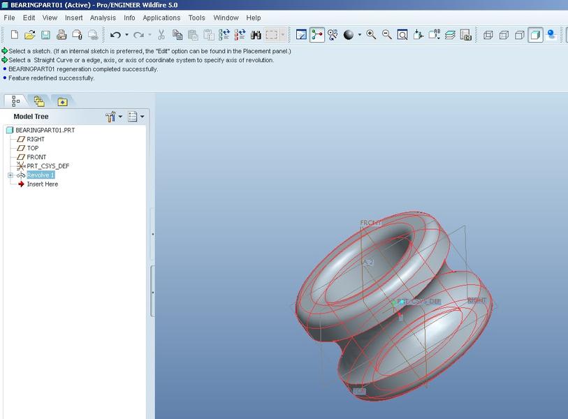
- Pro/ENGINEER - package software for solving engineering and design tasks.
These programs provide wide-ranging capabilities for designing various parts, from simple to geometrically complex.
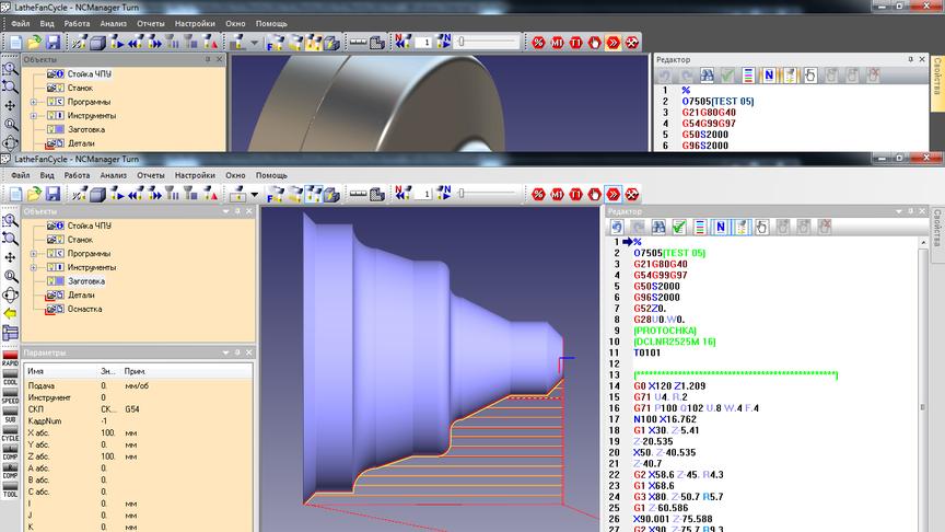
CAM software for generating the control program:
- SprutCAM - domestic software for creating G-code for turning any parts and products;
- Fusion 360 - a comprehensive system for both design and setting tasks for machine control;
- EdgeCAM - efficient software for generating control programs for a lathe.
These programs transform the model created in CAD software into understandable code for the machine.
Important! To save resources, you can install comprehensive packages that combine CAD/CAM functions. For example, AutoCAD or "KOMPAS-3D".
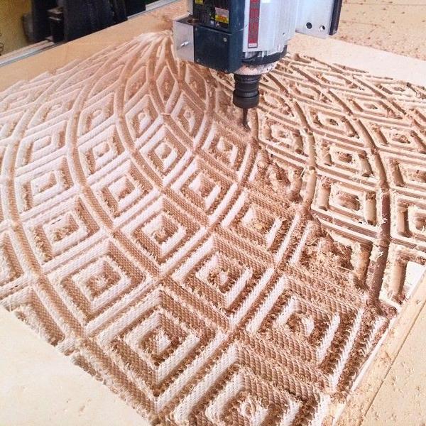
For CNC Milling Machines
Depending on the tasks faced by the technologist, different software for working with a milling machine is selected. To create sketches for flat cutting:
- CorelDraw - a graphic editor for vector images;
- LibreCAD - a program that creates 2D drawings;
- Adobe Illustrator - a program for creating and processing vector images.
For working with 3D models, you can use the same software as for turning machines.
You should also consider using programs such as:
- MasterCAM - software for 2D/3D design and generation of control commands for a machine;
- ArtCAM - a system that works with vector and raster graphics, allowing to create movement trajectories for milling relief surfaces;
- Mach3 - a program for controlling a milling machine based on the Windows OS, allowing to create custom codes, manage milling in six axes, generate G-codes.
Writing Programs for CNC Machines
In order to create a program that will implement the engineering development, the technologist must be proficient in a special code, similar to C# or Basic. This is a specialized G-code that control systems of machines with numerically programmable control can recognize.
G-Codes
G-codes contain a digital marking from 00 to 97, each of them corresponding to a specific operation or setting of the machine - from linear and circular movements, certain planes, input of metric data to correction and control of tool and engine speeds.
G-Code Blocks
Commands for CNC machine control are grouped into blocks. They are written in one line and the control system reads them sequentially from left to right. If there are not enough lines, the code will be continued in the next one, and the machine will switch to it.
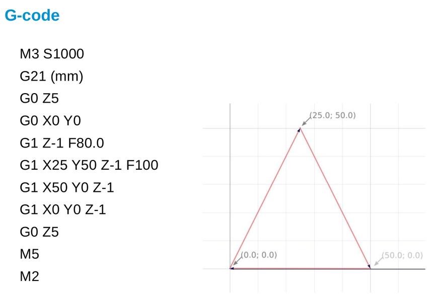
Examples of blocks:
- G17 G54 G90 - this block sets the parameters (plane, starting point, and absolute values);
- G0 X-19 Y-19 - instant movement to a point with specified coordinates;
- G1 XZ Y3 F600 - linear movement of the tool to a point with specified coordinates and rate feed of 600 mm/min.
Operators and technologists know G-codes by heart, so it is easy for them to quickly form the necessary programs.
G-Code Programs
Commands are given sequentially and logically, so the program usually consists of stages:
- Start.
- Tool loading.
- Main spindle startup.
- Coolant feed.
- Tool movement to the initial position.
- Processing start.
- Coolant shutdown.
- Main spindle stop.
- Returning the main spindle to the initial position.
- Program completion.
If a series of workpieces is to be processed, commands from 2 to 9 will be repeated.
Modal and Address Codes
Modal codes are necessary to activate and deactivate certain machine functions, such as cooling or spindle startup.
Address codes include coordinates for tool movement.
The most Common G-Codes
Operators or technologists most often use codes that denote the most typical movements:
Code | Command | Content |
G0 | Rapid movement | The machine uses both axes to most quickly move the tool to the desired point |
G1 | Linear motion | Moves the tool in a straight line |
G2, 3 | Clockwise/counter-clockwise arc | Provides smooth tool movement to the specified coordinates through intermediate ones, which define the arc |
G17, 18, 19 | Plane designation | It gives the machine a command to execute an arc movement in a specific plane |
G43 | Tool length compensation | Sets the length of the tool related to the Related PostsAdd ReviewPopular Post |
